
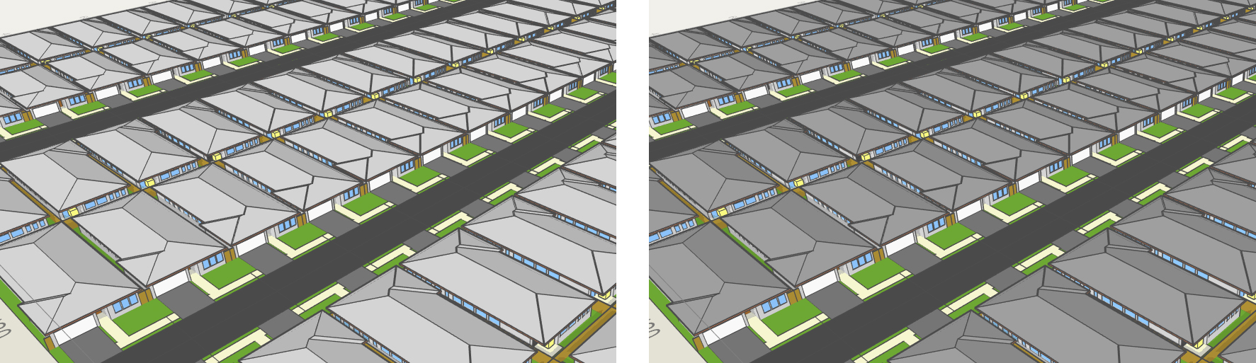
Throughout Australia a number of new housing innovations continue to be delivered and tested in emerging communities and in suburbs experiencing redevelopment. Some of the more topical housing forms are the 'small lot' housing products which are typically built on 200m to 400m lots and can include terraces, duplexes and detached housing forms.
The thermal performance of each dwelling type as well as the broader performance of suburbs which contain a high proportion of small lots can be measured through AKLFlowDesigner. This article will seek to test a range of different design responses and their associated thermal performance at the single lot level. This article is focused on a typical single floor small lot dwelling and will investigate:
• The cooling benefits of roof insulationHowever, one the key advantages of using AKLFlowDesigner is that the program already contains the most important information relevant to these matters and can provide design insights without needing to develop new or customised data sets. The intuitive interface and familiar tool set allows users to undertake important simulations without needing a detailed understanding of the above noted concepts. Accordingly, this article will present a streamlined approach to determining climatic design performance with future articles providing more detailed scientific exploration of these concepts.
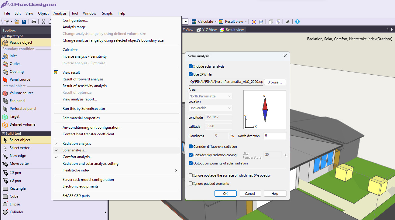
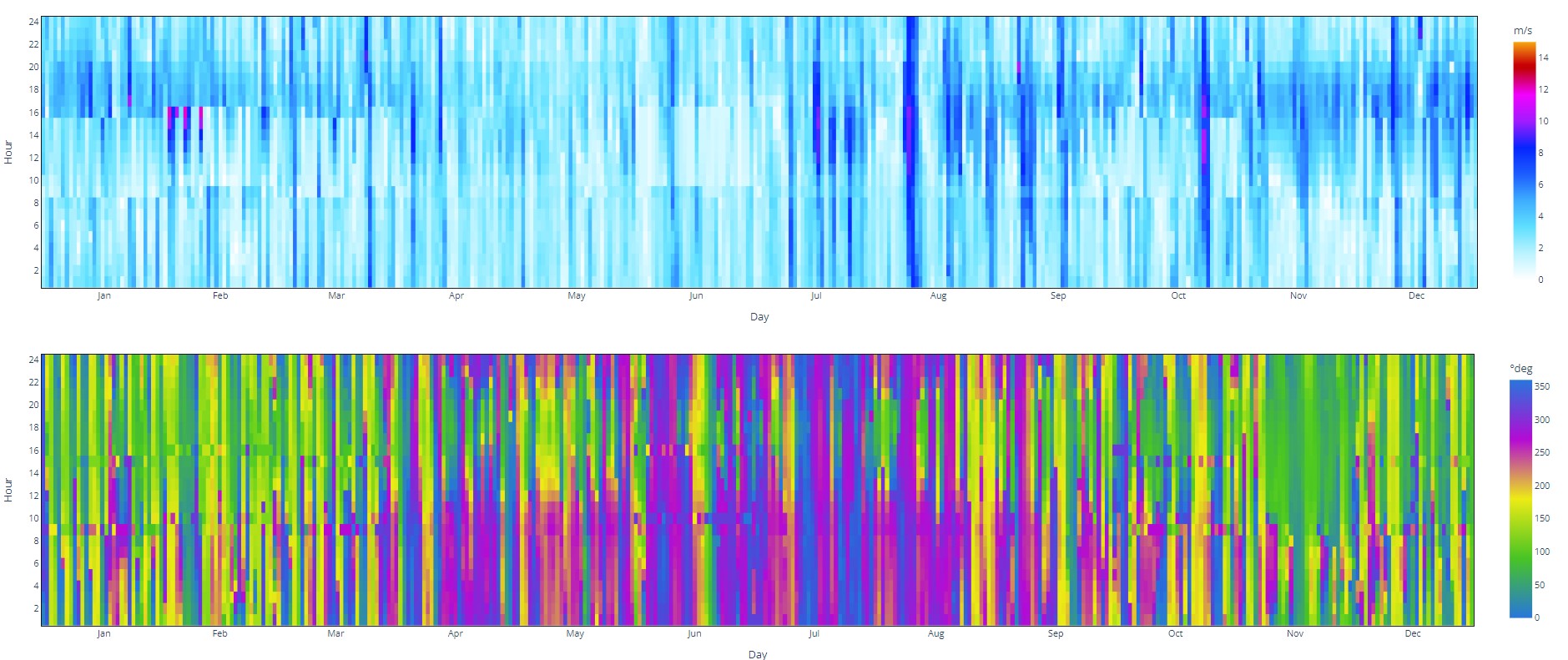
The climatic conditions of any particular location in Australia can be recreated digitally using a number of parameters including temperature, humidity, wind speed, wind direction, cloud clover, radiant heat energy etc. EnergyPlus Weather (EPW) files contain specific climate information including many parameters which can be imported into AKLFlowDesigner using the solar radiation assessment option.
An intuitive way of viewing EPW files can be found via the online resource provided through the Berkley University of California Centre for the Built Environment’s online web CBE Clima Tool: a free and open-source web application for climate analysis tailored to sustainable building design. Version: 0.8.12. Betti G., Tartarini F., Nguyen C., Schiavon S. (2022).
This website not only allows for the review of multiple data sets, it also provides a world map identifying multiple locations where weather information has been recorded and compiled into EPW file formats. From this website you can download EPW files and use them in AKLFlowDesigner. The below image from the CBE Clima Tool website shows the extent of weather station data availability in Australia.

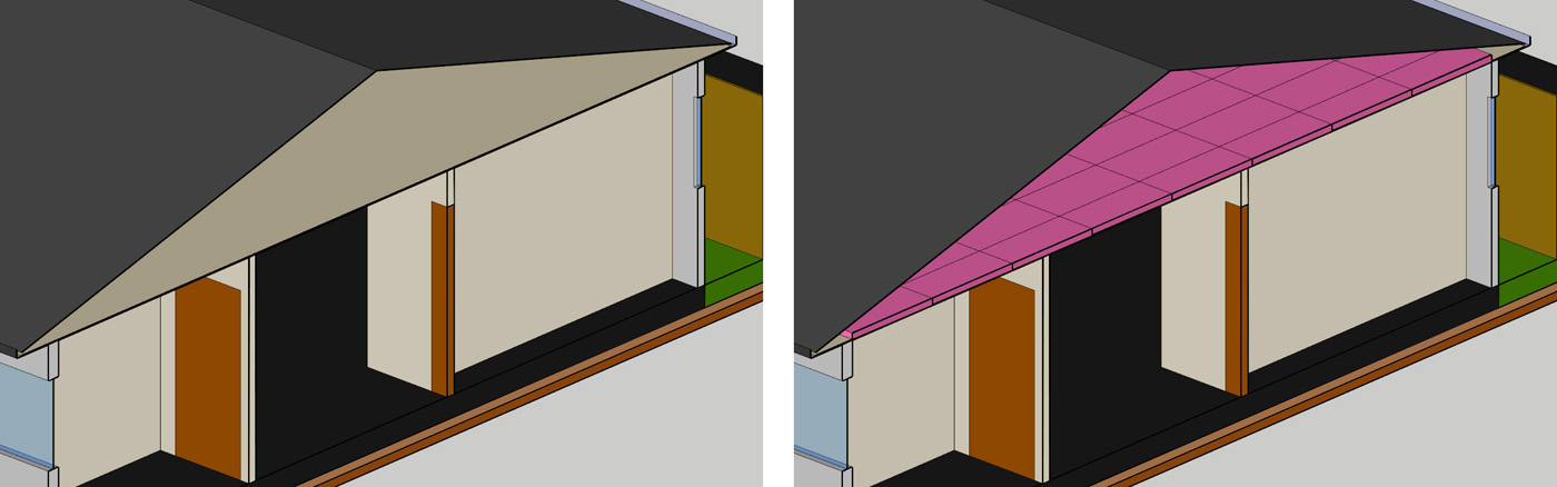
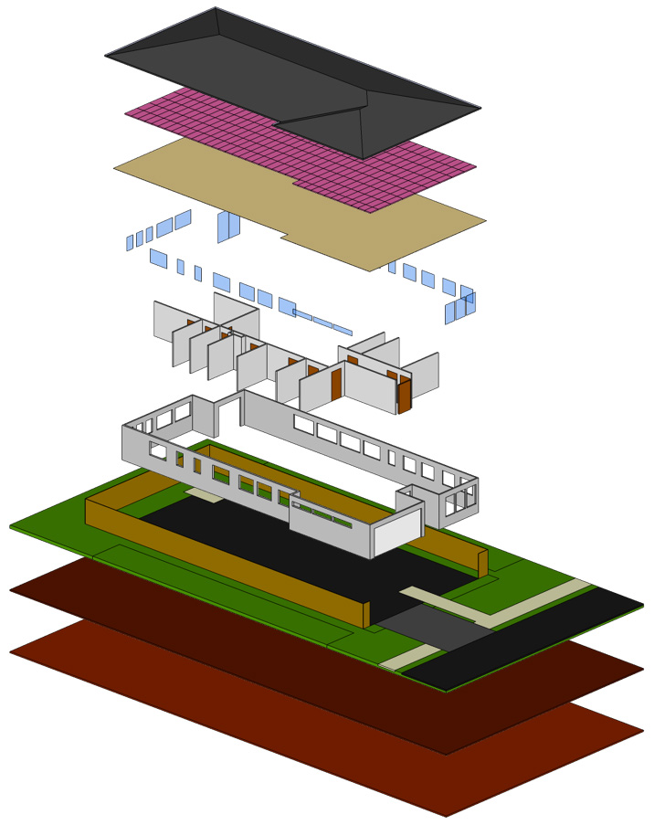
The thermal properties of each construction material must be known to accurately simulate the performance of the reference design. Some analysis systems rely on a material’s SRI, or R / U values to determine thermal performance, however these values may not capture all of the thermal impacts related to the geometry of adjoining structures, the depth of overshadowing, humidity and material heat loss via convection. For example, it is difficult to determine the thermal performance of angled roofs which may be ventilated and contain insulation. See below the arrangement of a tile roof and ceiling both with and without insulation which would challenge many other software packages, but is inherently easy to simulate in AKLFlowDesigner.
An example of this would be determining the relative benefits of clear float vs heat absorbing green tint vs low-e multilayered glass.
AKLFlowDesigner comes with an extensive library which covers many different types of construction related materials. The library can be simply expanded to include any material type and Envision Urban and AKL continue to work together to build a library of key Australian design materials. The upcoming ‘Thermal Design and Materials’ article on this website will include a more extensive discussion of building materials and how they affect the performance of buildings.
The specific performance of construction materials is often published by the manufactures and can be acquired through a simple web search. In addition to this a number of industry groups and bodies also maintain and publish this information.
The below is an example of an industry web page which provided specific material information. https://www.greenspec.co.uk/building-design/insulation-materials-thermal-properties/|
|
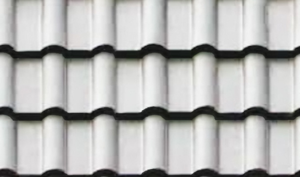
Light
Coloured Tiles
 |
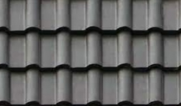
Dark Coloured Tiles
 |
|
Density |
1890 (J.(kg.K) |
1890 (J.(kg.K) |
|
Specific heat |
1000 (kg/m3) |
1000 (kg/m3) |
|
Thermal conductivity |
0.836 (w/m.k) |
0.836 (w/m.k) |
|
Absorptivity |
0.9 |
0.9 |
|
Reflectivity |
0.1 |
0.1 |
|
Solar absorptance |
0.27 |
0.943 |
| Solar reflectivity | 0.73 | 0.057 |
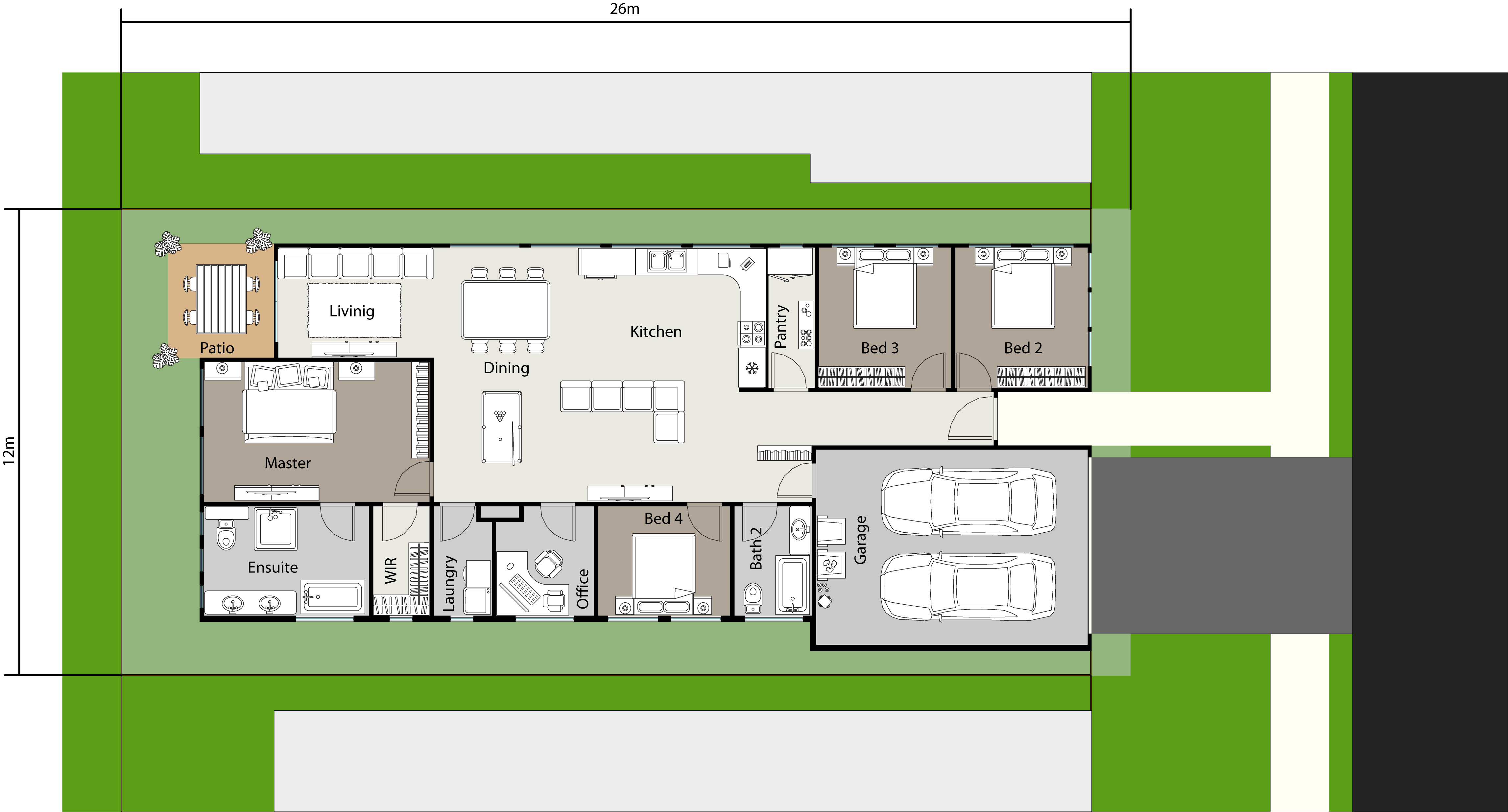
A baseline should be established which can be used as reference point from which all future scenarios are compared. For this project, a base case which uses the solar information from the Paramatta EPW file is applied. Specifically, 10:00am on the morning of 21 January 2023 has been selected. The observed ambient temperature is 29º C with a relative humidity of 50%. Importantly, this baseline simulation does not include access to a wind resource and no breezes are present. To undertake this simulation in AKLFlowDesigner the ‘Pseudo Windless’ setting must be chosen.
Before specific results and
measurement are derived, it is worthwhile reviewing all the
calculated data which informs the outcomes of the simulation. Most
of these are based on the transfer, retention and dissipation of
thermal energy. Whilst many data layers exist in the simulations,
four key metrics are presented in the below images to represent
some of these energy insights.
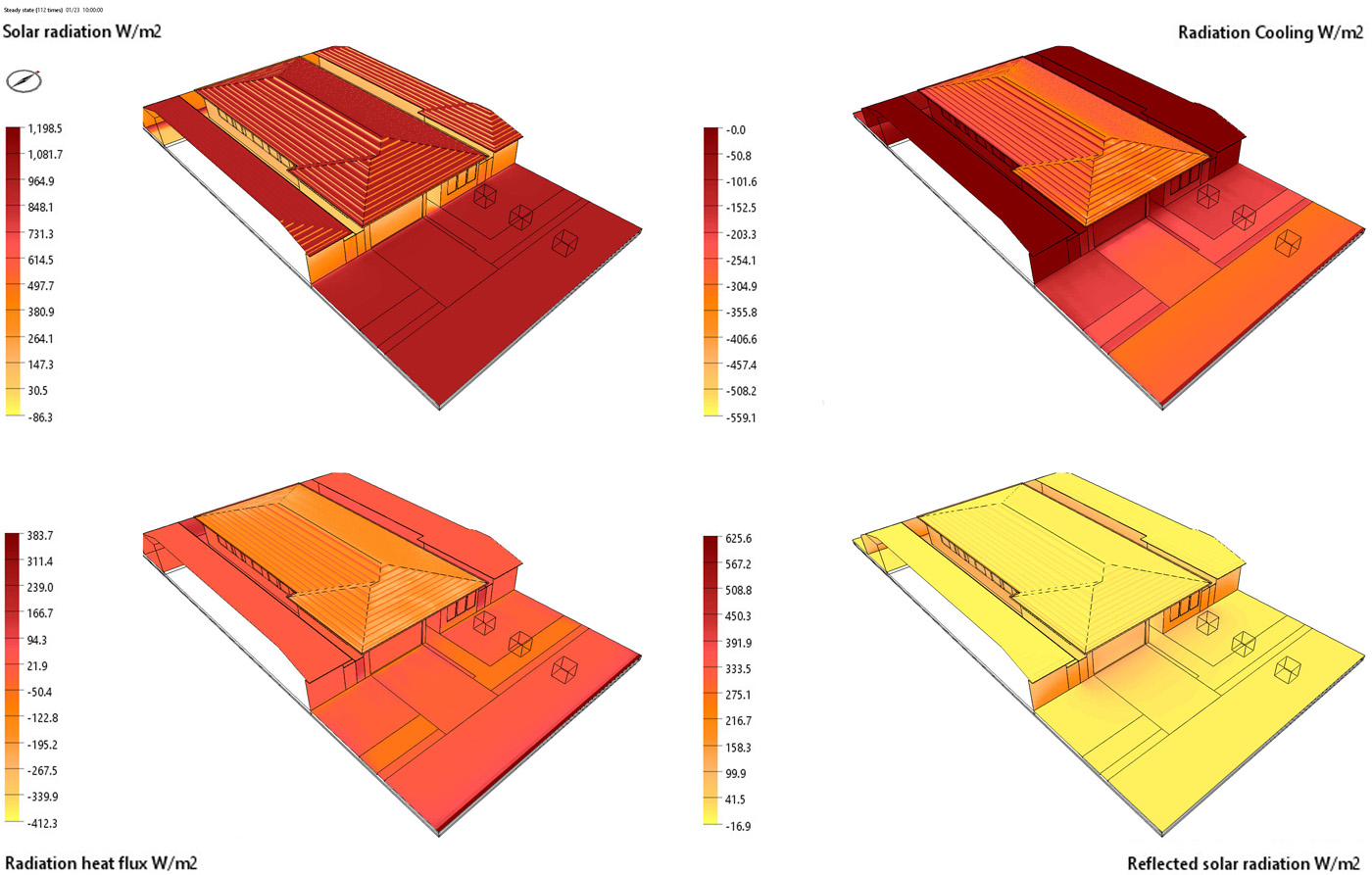
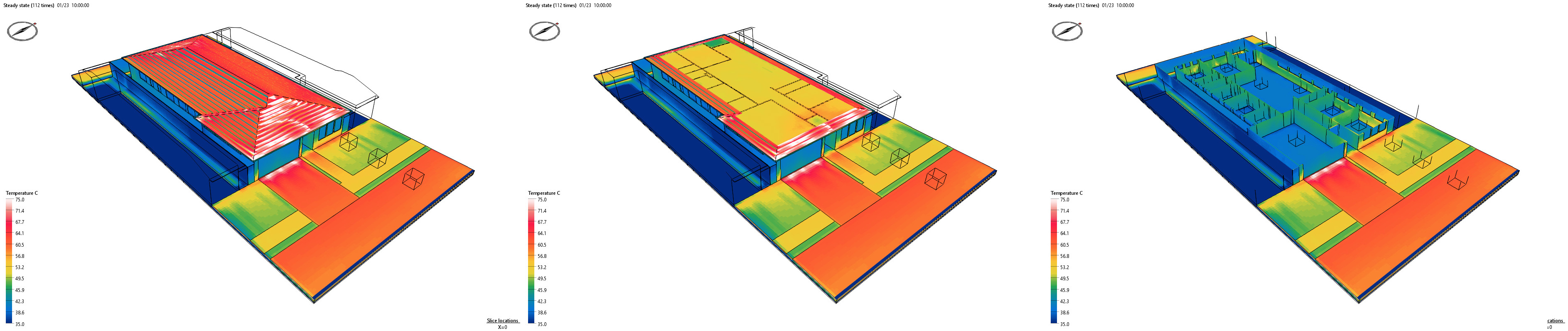
The below images show the surface
temperatures of both the interior and exterior and the heat of
each individual building feature based on its location, size,
materiality and design. Significant heat is seen on the exterior
drive way, road, and paved footpaths. However, the highest
concentration of heat can be observed on the eastern facing side
of the roof which receives the highest direct amount of solar
radiation. AKLFlowDesigner allows you to view all information
within the model by live sectioning along any axis.
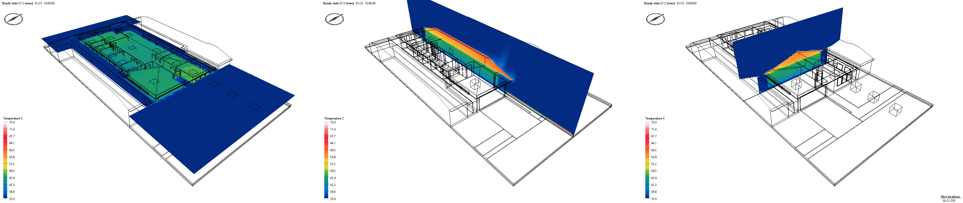


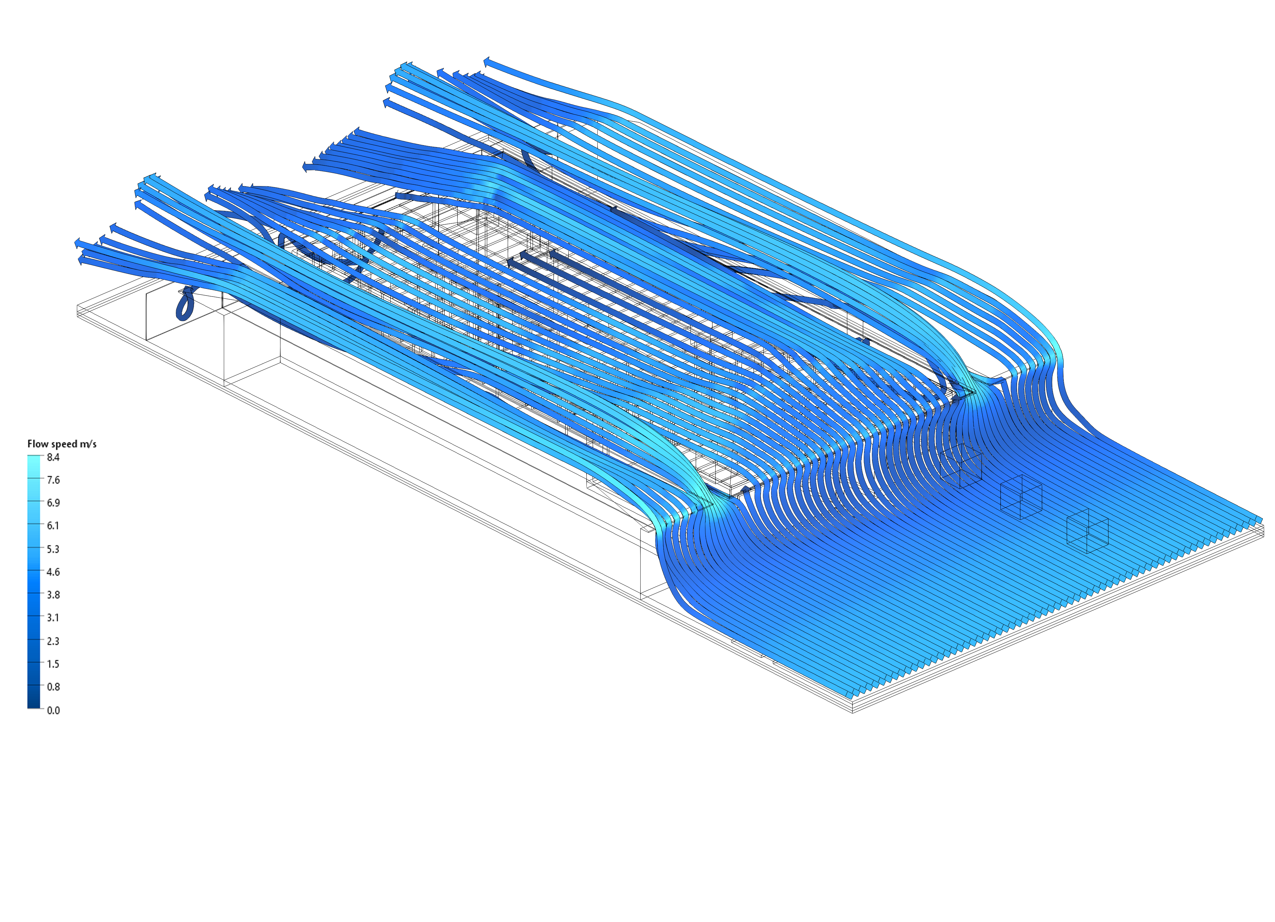
The below images show four different velocities of breeze engaging with the reference design. The loss of heat from a surface due to breezes passing over it is known as convection loss. In additional to convection loss, AKLFlowDesigner is above to visually represent the radiant convection heat flux or the amount of energy removed from a surface. These are shown for each of the below scenarios with a clear trend emerging showing that increased speeds increase the thermal loss of the roof surface. Again, the observed ambient temperature is 29º C with a relative humidity of 50%.
Further, it appears that with the reference design in this location, the potential reduction in thermal stress due to breeze access is at least as significant as the chosen roof colour.
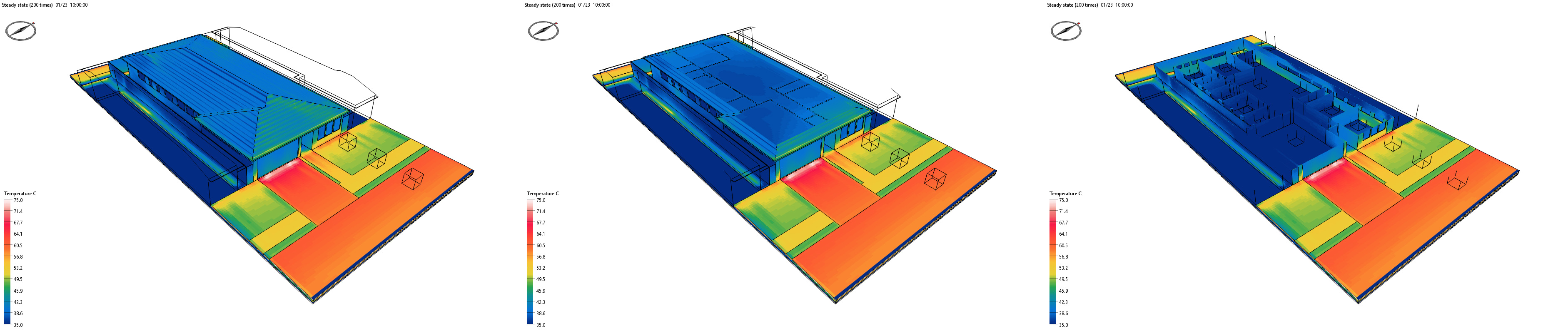
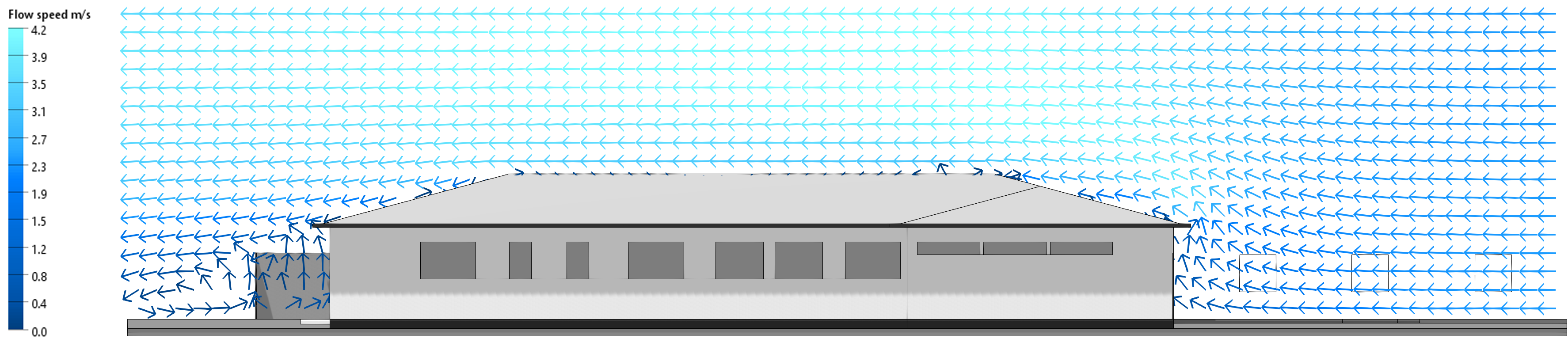
Opening the doors and windows in different combinations throughout the reference design achieves different levels of human comfort and associated temperature levels through the structure. This is due to the introduction of external breezes which are typically at the prevailing ambient temperature which is much cooler than the radiant internal temperature within the building.
The below image shows a closed scenario on the left with the breezes going over the building and accelerating over the roof surface. The image on the right highlights breezes from the same origin point but the scenario includes and open front door and an open rear door. This results in the breezes passing through the interior, albeit at a reduced velocity.
For each project the frequency, direction, temperature and speed of seasonal breezes should researched and analysed. Most of the time, weather readings will be recorded in only a single location within a particular precinct. It is important to note that the conditions recorded at a single location will be influenced by the movement of air relative to the elevation and aspect of the local terrain. Accordingly the orientation, design and materiality of small house products should be optomised to capture summer afternoon breezes and efforts should be applied to ensuring that they are not inappropriately located in areas which do not have access to winds.
To provide additional insights into
the behaviour of breezes through and around small lot housing
products, the below scenario has been prepared to evaluate the
benefits of opening the front door and the rear door indicated
below with the blue 'open door' icons. Each window and door within
the reference model can be easily opened or closed by simply
turning on and off each feature in AKLFlowdesigner. This allows
for every conceivable scenario to be tested and analysed.
The above shows a series of cross sections that help understand the relative comfort achieved in both the internal rooms and external areas. The temperature and wind velocity slices show a strong correlation between rooms which receive cross ventilation and those with reduced temperatures. The wind speed slice shows that the speed of the breezes within the form are of higher velocities near the opened doors but also that breezes within the lounge room are still of a reasonable velocity. The Mean Radiant Temperature (MRT) shows some correlation with the temperature slice but given the enclosed nature of the space, the cooling effects of breezes are less clear. Therefore it is suggested that MRT has limited utility in determining interior comfort levels.
The results show that passive cooling significantly increases with the increased velocity of available breezes. The design of the windward side of the house and size and location of the primary opening (the front door in this example) is particularly important when it comes to encouraging cross ventilation.
The below diagrams include additional details for the above scenarios and including an extra configuration for comparitive assessment. The fifth diagram set described as ''rear doors and windows open' with a 4.8 m/s breeze tests a scenario where many of the windows are opened on the side of the house and the rear door is open but the front door has been left closed. The results suggest that the relative cooling achieved may not be sufficient without a wide opening to the windward side of the structure.
Therefore, extra design emphasis should be placed on the entrances and openings on the windward side to ensure that whilst cross ventilation is encouraged, visual and acoustic privacy within the house is also maintained. AKLFlowDesigner makes the testing of specific design responses to these types of problems quick and efficient. Changes to the design can either be completed within AKLFlowDesigner utilising its own modelling tools, or specific elements can be removed and re-imported from external applications including SketchUp, Revit etc.
Australia continues to endure extreme summer weather conditions including very high temperatures and humidity levels. Seasonal storms and cyclones compound this problem when they damage or destroy power line infrastructure and disrupt electricity supply. The result is potentially extensive periods of time where residents are unable to avoid uncomfortably hot conditions and will become susceptible to heat stress, fatigue and in extreme instances fatalities may occur. Whilst on site solar power generation can be configured to provide some backup power contingency in the case of extended blackouts, the retention capacity of onsite batteries are unlikely to support air conditioning usage for multiple days.
Therefore, the layout and materiality of housing products are vitally important and architectural expertise is crucial to ensuring all design considerations are appropriately considered when planning, assessing or developing new housing products. Well designed small lot products can achieve a good level of thermal comfort for occupants if they are well located and orientated.
Accordingly, the most robust software solutions should be utilised by architects, landscape architects and planners to ensure that all design assumptions are validated. AKLFlowDesigner provides the perfect platform to absorb common Australian environmental data sets, import design files from a range of platforms, and produce outputs which interrogate, highlight and confirm environmental performance.
The above analysis provides a robust and accurate simulation of a built form reference design against the typical climatic conditions of Parramatta. However the mere measurement of temperature and wind speed are not in their own right appropriate criteria with which to judge human comfort.
Accordingly, Article 3 will built on the analysis prepared in this article and go further to provide a history on the evolution of various comfort criteria, and also suggest some performance benchmarks which may be appropriate for adoption in the review of development applications, and the certification process for a range of environmental accreditations.
Article 3 will also provide detailed information on the following topics.
Time to prepare models and undertake simulations : Approximately 10 hours
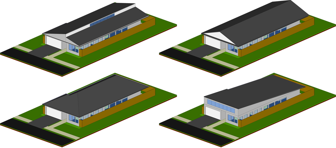
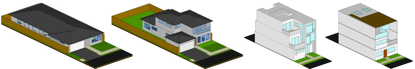
Investigate the relationship between standard planning controls and thermal performance. Specifically, determine what, if any impact controls such as setbacks and site cover ratios have on the internal and external areas of the reference design. Changes may be made to the dwelling to test what if any benefit may be achieved by reducing the footprint of the dwelling. Successful changes will retain or reduce the internal temperatures of the building and the external patio area. The below shows some typical examples of setback configurations which may be considered.
Time to prepare models and
undertake simulations : Approximately 4 weeks
The reference model has a hip roof design, however many other roof forms are common throughout Australia. Change the roof form to see what, if any impact the design and shape of the roof has on the internal and external temperature of the dwellings. Also create a roof form which incorporates a weather proof ceiling opening via operable windows or other form. Determine what, if any thermal relief the ceiling opening provides in a 'pseudo windless' scenario when all other openings are closed.
Time to prepare models and
undertake simulations : Approximately 1 term for third+ year
students
Identify a recent or emerging residential estate with a variety of small lot housing products. Form a group of four students and have each student prepare a 3D model for a particular product based on site observations and online plans. Ensure that the housing types are generally similar in terms of height, size and setbacks. Apply materials with the same thermal attributes to all models ie. use the same timber, plaster, concrete, ceiling tiles etc. Run a thermal simulation using AKLFlowDesigner based on the same agreed upon climatic conditions / time of day / date and determine the temperature in each of the habitable rooms for each of the four chosen dwellings.
Time to prepare models and
undertake simulations : Approximately 4 weeks
Using the AKLFlowDesigner library of trees and shrubs, plant out the back yard, front lawn, and footpath with a variety of species at varying sizes. Using AKLFlowDesigner determine what the impacts of the additional planting was on the temperature, humidity and wind speed of the exterior arreas. What if any impact did the additional planting have on the internal temperature of the reference design? What was the difference in the wind speed, temperature and humidity of the breeze when it entered at the front of the property vs the conditions at the rear boundary.